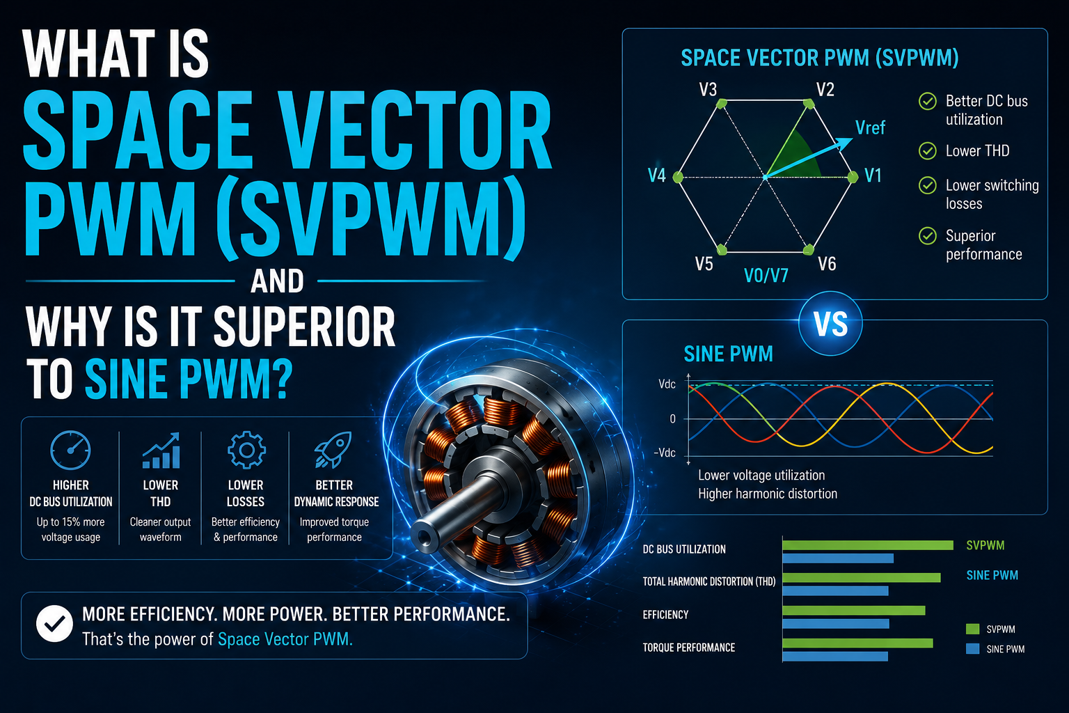
⚡ What is Space Vector PWM (SVPWM)?
Space Vector PWM is an advanced method of generating switching signals for a 3-phase inverter.
Instead of treating each phase separately (like sine PWM does), SVPWM:
Treats the 3-phase system as a single rotating voltage vector in a 2D plane (α-β reference frame).
It mathematically calculates how to synthesize the desired voltage vector using the inverter’s 8 possible switching states.
🧠 Basic Idea
A 3-phase inverter has:
- 6 active voltage vectors
- 2 zero vectors
→ Total 8 switching states
SVPWM:
- Determines the desired rotating voltage vector
- Identifies which sector (1–6) it lies in
- Combines two adjacent active vectors + zero vectors
- Calculates exact time durations for each
Result: The inverter output closely approximates a rotating sinusoidal field.
📈 What is Sine PWM (SPWM)?
In sine PWM:
- Each phase is modulated independently
- A sine wave is compared with a triangular carrier
- Switching is generated per phase
It is simple and intuitive — but not optimal.
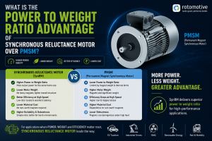
🚀 Why SVPWM is Superior to Sine PWM?
1️⃣ Higher DC Bus Utilization (Major Advantage)
This is the biggest technical benefit.
| Method | Maximum Fundamental Output Voltage |
| SPWM | ~0.785 × Vdc |
| SVPWM | ~0.907 × Vdc |
👉 SVPWM gives ~15% more voltage output from the same DC bus.
Why this matters:
- Higher achievable speed
- Better torque at high RPM
- Smaller battery or lower DC bus possible
- Critical in EV traction systems
2️⃣ Lower Harmonic Distortion
SVPWM:
- Produces lower Total Harmonic Distortion (THD)
- Better waveform quality
- Reduced motor losses
- Lower heating
This improves:
- Efficiency
- Torque smoothness
- Acoustic noise
3️⃣ Better Torque Control
Because SVPWM:
- Controls the voltage vector directly
- Aligns perfectly with Field-Oriented Control (FOC)
It provides:
- Smoother torque
- Faster dynamic response
- Better transient performance
Essential for:
- EV traction
- Robotics
- CNC machines
4️⃣ Reduced Switching Losses (Optimized Sequences)
SVPWM:
- Uses optimized switching sequences
- Minimizes unnecessary switching transitions
- Can reduce switching losses
5️⃣ More Suitable for High-Performance Drives
SPWM:
- Easy to implement
- Good for basic industrial drives
SVPWM:
- Used in:
- EV inverters
- PMSM drives
- Induction motor vector control
- Servo systems
📊 Visual Concept Difference
SPWM:
Phase-based control
(3 separate sine comparisons)
SVPWM:
Vector-based control
(Single rotating vector synthesized geometrically)
Think of SPWM as 3 independent systems.
Think of SVPWM as one coordinated vector system.
📌 Practical Example in EV
Suppose DC bus = 400V
With SPWM:
- Max line voltage ≈ 314V
With SVPWM:
- Max line voltage ≈ 362V
That extra voltage:
- Increases maximum base speed
- Reduces field weakening requirement
- Improves top speed performance
This is why almost all EV traction inverters use SVPWM.
⚠️ Is SVPWM Always Better?
Nearly always in modern applications — but:
- It is more computationally complex
- Requires digital control (DSP / MCU)
- Harder to implement in analog systems
Today this is not a limitation.